Last week, I ordered a whole bunch of Electret microphones from Sparkfun. I thought I could add some cool noise sensors around the rover I've been building. They come in and I start researching how to use them when I realize that I've made quite the mistake. These little microphones are way too weak for the Arduino to read anything from. What I should have purchased was this breakout board since it has a 100x opamp that amplifies the signal for the Arduino. The damage was done though and I wanted to see if there was anything I could do to make these things work.
After much research online and toying around, I found this circuit and tried it to see if it would work.
Here it is on the breadboard:

When I first set it up, it didn't work and I couldn't figure out why. I then realized that I just didn't have power going to the board. Nice and simple mistake. After fixing that, it seemed to return some value of 850. Trying a different microphone gave me a different start value. I set up my program so that it would get the ambient noise average before it started so I didn't have to worry about setting a value for each microphone. After I got that setup, I simply check if the sound is higher than the ambient noise and flash an LED if it is. That all seemed to work, so I went ahead and created a more portable version of it for my little rover.

Once that was done (and tested to make sure it still worked (it did)), it was Dremel time.

All tested and working well. Here's a little video that shows it in action.
http://www.youtube.com/watch?v=ZHyVWfwPMOs
I still don't think it's quite right. It should have a much larger range than it does, but this will do for now. I can toy with this until I find a better circuit to use or just order the breakout board that Sparkfun sells.
After much research online and toying around, I found this circuit and tried it to see if it would work.
Here it is on the breadboard:

When I first set it up, it didn't work and I couldn't figure out why. I then realized that I just didn't have power going to the board. Nice and simple mistake. After fixing that, it seemed to return some value of 850. Trying a different microphone gave me a different start value. I set up my program so that it would get the ambient noise average before it started so I didn't have to worry about setting a value for each microphone. After I got that setup, I simply check if the sound is higher than the ambient noise and flash an LED if it is. That all seemed to work, so I went ahead and created a more portable version of it for my little rover.

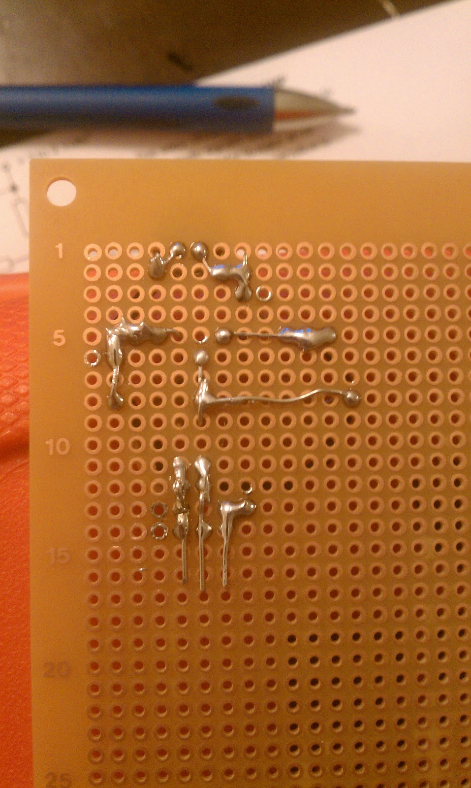 |
| The 3 pins are Signal, +5v, Ground. |
Once that was done (and tested to make sure it still worked (it did)), it was Dremel time.

 |
| Now you can see why I added 3 pins :] |
All tested and working well. Here's a little video that shows it in action.
http://www.youtube.com/watch?v=ZHyVWfwPMOs
I still don't think it's quite right. It should have a much larger range than it does, but this will do for now. I can toy with this until I find a better circuit to use or just order the breakout board that Sparkfun sells.
3 comments:
Thanks for the post!
good day sir,can you post the code used in this circuit?
I've used the same circuit to control claps. I see you only have 1 capacitor, and that's a difference between your board and actual schematics.
Removed capacitor and now claps can be registered.
Post a Comment